
Technical Case Study · Public Infrastructure · Sri Lanka
Kandy Multimodal Transport Terminal BIM Coordination: LOD 350, MEP, CCTV and Construction Documentation
How multidisciplinary LOD 350 modelling, MEP coordination, specialist BIM content, CCTV placement review, documentation and visualization supported the 1,076,000 sq. ft. Kandy Multimodal Transport Terminal.
The short answer
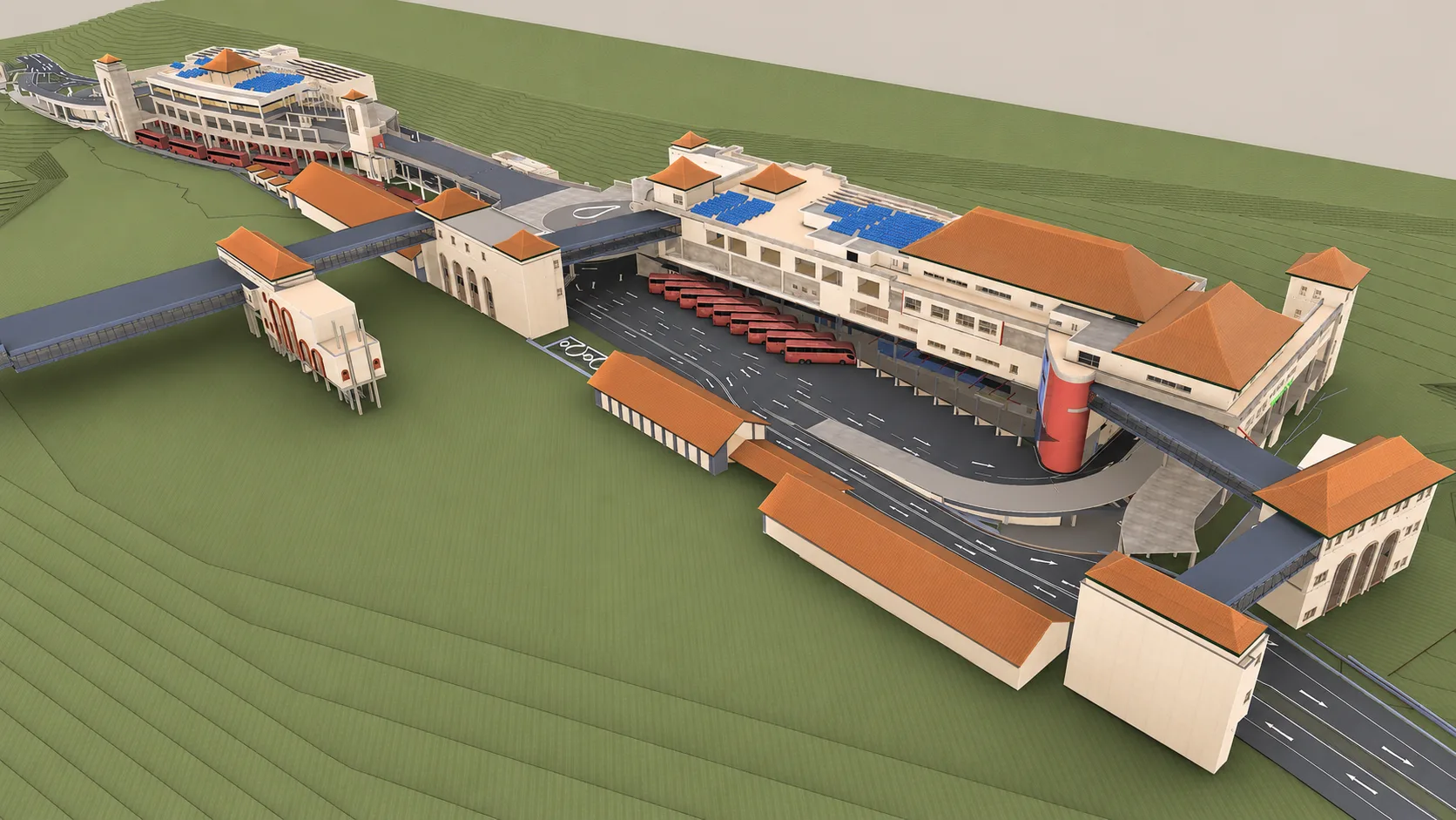
The Kandy Multimodal Transport Terminal (KMTT) required architecture, structure, MEP systems, specialist equipment, landscape information, security devices and construction documentation to be reviewed as one coordinated digital environment. IBS Projects supported the 1,076,000 sq. ft. project with LOD 350 architectural and structural BIM, coordinated HVAC, plumbing, electrical and fire-protection modelling, machine-room coordination, specialist BIM content, CCTV placement review, documentation and visualization.
Why BIM coordination mattered at KMTT
The Kandy Multimodal Transport Terminal is a major public-transport development in central Kandy. Public World Bank information describes the project as the redevelopment of the Good Shed terminal to integrate rail, bus, three-wheeler and pedestrian movement, with the broader objective of improving accessibility, efficiency and safety in the city's public-transport system (World Bank, 2021).
That functional ambition creates a demanding coordination environment. A multimodal terminal is not a single-purpose building. Passenger circulation, transport operations, architecture, structural systems, building services, vertical transportation, security systems, machine rooms, public spaces and external interfaces all have to coexist within one facility. A decision in one discipline can affect several others.
The source article records that IBS Projects (Pvt) Ltd collaborated with ArchiCAD (Pvt) Ltd to provide BIM support for MAGA Engineering. The source scope includes architectural, structural, MEP and landscape modelling, clash coordination, CCTV camera-location review and visualization. The published IBS Projects portfolio adds further detail: a 1,076,000 sq. ft. project area, LOD 350 architectural and structural modelling, HVAC, plumbing, electrical and fire-protection BIM, detailed machine-room modelling, specialist equipment, custom families, schedules, detailed shop drawings and visual outputs.
The core challenge: coordinating multiple disciplines in a dense transport environment
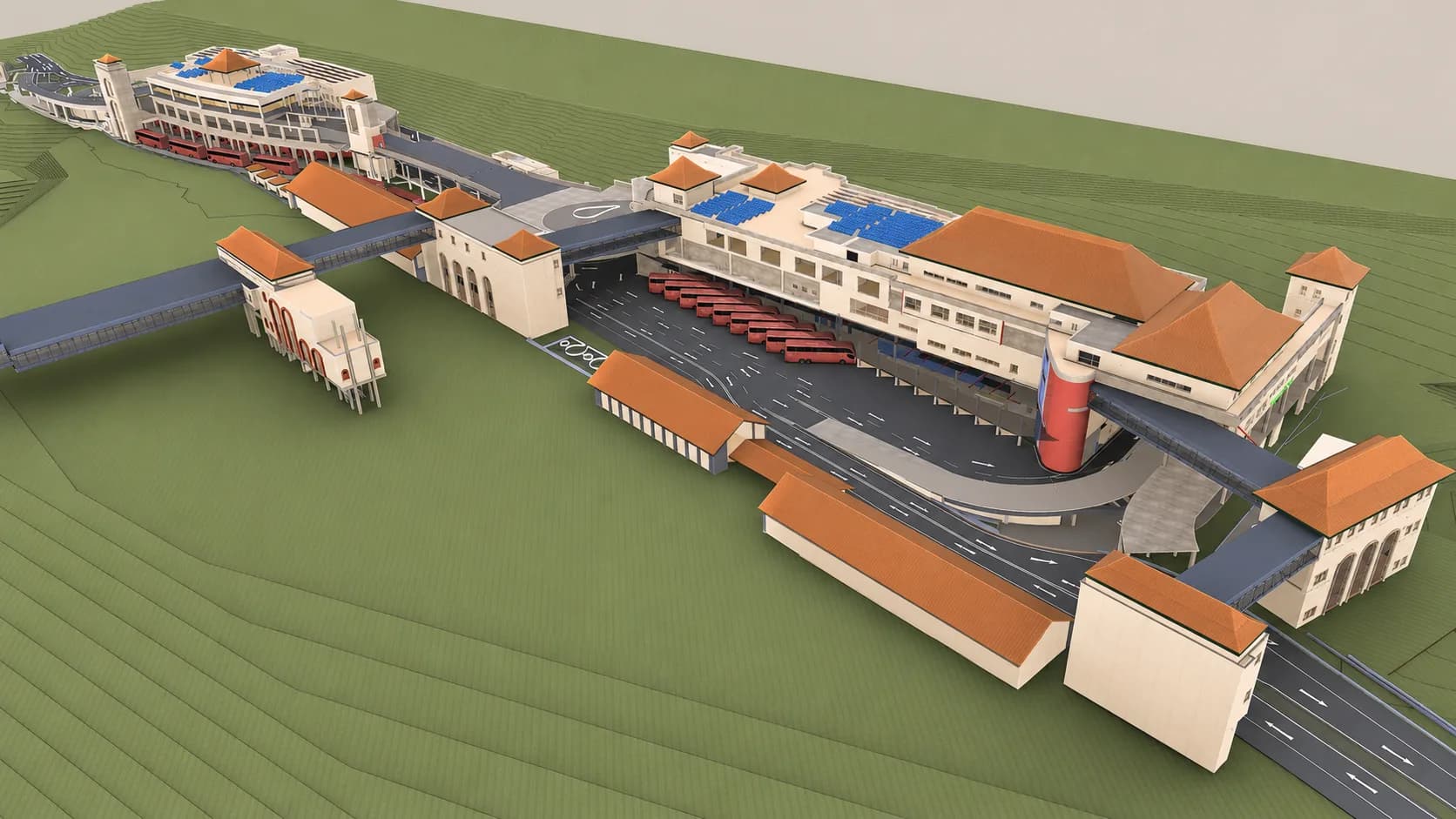
Large transport terminals concentrate many systems into constrained spaces. Structural beams and columns establish the physical framework, while ceilings, ducts, pipes, cable routes, fire-protection systems, vertical-transport equipment, architectural finishes and passenger circulation compete for the remaining space. When these systems are reviewed only through separate two-dimensional drawings, conflicts can be difficult to identify until construction or installation.
The project source identifies this as a central KMTT challenge. The project team required a coordinated digital model that could visualize the proposed design, expose potential clashes and support decisions before site work progressed. The value of BIM was therefore not the existence of a 3D model by itself, but the ability to review relationships between systems before they became physical constraints on site.
A coordination model also needs to preserve responsibility boundaries. BIM can reveal geometric conflicts, access problems and interface risks, but final engineering design, statutory compliance, equipment selection and construction acceptance remain governed by approved project information and the responsible disciplines. The model supports those decisions rather than replacing them.
Multidiscipline BIM development across the KMTT scope
LOD 350 architectural and structural modelling
The IBS Projects portfolio records architectural and structural BIM development at LOD 350. The architectural model translated approved design information into a coordinated digital representation of the terminal's building form, spaces, openings, circulation areas and interfaces. The structural model represented the principal structural elements needed for coordination with architecture and building services.
LOD 350 is particularly useful for coordination because element interfaces with adjacent or dependent elements are developed sufficiently for spatial review. BIMForum's LOD guidance describes LOD 350 as supporting construction-level coordination while also emphasizing that the project's BIM Execution Plan or contractual requirements control the exact information required for each element (BIMForum, 2025).
For KMTT, the practical purpose was not to imply fabrication-level detail for every object. It was to provide enough reliable geometry and interface information to evaluate where building systems meet, pass through or compete with one another.
MEP modelling and machine-room coordination
The published KMTT scope includes HVAC, plumbing, electrical and fire-protection BIM together with detailed machine-room modelling. These systems are among the most coordination-intensive parts of a large public facility because routes, equipment, clearances, supports, access zones and maintenance requirements have to fit around structure and architecture.
Machine rooms concentrate even more interfaces. Equipment footprints, duct and pipe connections, electrical clearances, service access and maintenance zones can create conflicts quickly if each discipline develops in isolation. A coordinated BIM environment allows these relationships to be reviewed together before installation.
Specialist equipment and project-specific BIM families
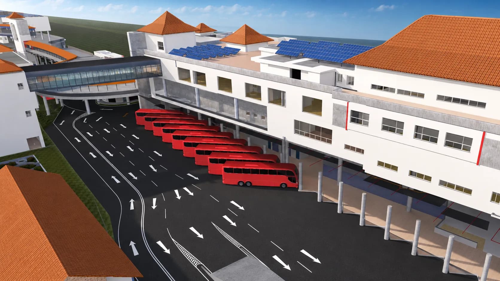
The portfolio also identifies specialist content including lifts, escalators and fuel tanks, together with custom BIM families for project-specific components. In a transport terminal, these elements are not decorative additions. They define circulation, operational interfaces, equipment clearances and service connections that affect surrounding systems.
Project-specific families are useful where generic content does not accurately represent the selected equipment. For coordination, the important information is the dimensional envelope, interface geometry and connection conditions that affect adjacent disciplines. Using project-specific content can therefore make clash review and documentation more reliable than using visually similar placeholders with incorrect geometry.
Landscape and external context
The uploaded source article includes landscape modelling within the project scope. On a multimodal transport project, external areas are functionally connected to the terminal: passenger approaches, pedestrian paths, drop-off zones, transport circulation and public-realm interfaces all influence how the facility operates. Representing that context helps stakeholders review the terminal as part of the wider development rather than as an isolated building.
Clash identification and coordination before construction
One of the clearest practical uses of BIM on KMTT was clash identification. Potential conflicts between services, structure, architecture and specialist equipment can be reviewed digitally while changes remain easier to evaluate.
A clash is not automatically a design error. Some intersections may be acceptable model conditions, temporary coordination states or issues that need discipline review. The important part is a repeatable coordination process that identifies, classifies, assigns and resolves relevant conflicts through the project team.
Combine current discipline information
Bring the latest architectural, structural and MEP information into a common coordination environment.
Review clashes and clearances
Check hard clashes and clearance-related conflicts around beams, columns, walls, shafts, ceilings, equipment and access zones.
Assign issues correctly
Route identified issues to the responsible discipline instead of changing another discipline's design without authority.
Update after approved decisions
Refresh the coordinated model as approved changes are incorporated and repeat the review as project information develops.
Coordinate specialist content
Review lifts, escalators, fuel tanks, machine-room equipment and project-specific families against surrounding systems.
Connect BIM to documentation
Use coordinated information to support plans, sections, schedules and detailed construction documentation.
Using BIM to review CCTV camera placement and security coverage
The source article identifies CCTV camera placement as a specific KMTT BIM contribution. Camera locations depend on more than simply attaching a device to a wall or ceiling. Useful coverage requires consideration of mounting position, viewing direction, field of view, physical obstructions and the geometry of the spaces being monitored.
By placing proposed camera positions within the coordinated model, the project team could review viewing directions against the terminal and parking-building geometry before installation. Columns, walls, ceilings, equipment and other obstructions can be considered spatially, giving the security design team a more informed basis than symbolic camera locations on a two-dimensional plan alone.
The BIM model supports that spatial assessment, but it should not be interpreted as independently certifying security performance. Final camera selection, lens characteristics, coverage criteria, privacy requirements and security-system acceptance remain subject to the responsible specialist designers, project specifications and approved equipment.
From coordinated models to construction documentation
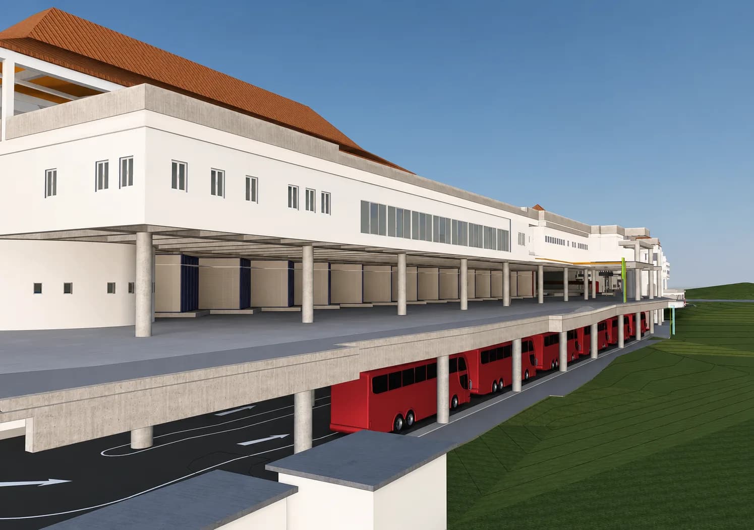
The published KMTT portfolio records schedules and detailed shop drawings as part of the delivery. This matters because BIM adds more value when coordination flows into usable project information rather than stopping at a 3D review model.
Plans, sections, schedules and detailed drawings can be generated or coordinated against the model so that changes are easier to track across multiple outputs. When model information, documentation and discipline revisions are managed consistently, teams have a clearer basis for reviewing interfaces, dimensions and construction requirements.
Model-derived documentation still requires checking against approved design information, project revisions and contractual requirements before issue. The coordinated model is an information source within the project workflow, not a substitute for formal review and approval.
Visualization as a technical communication tool
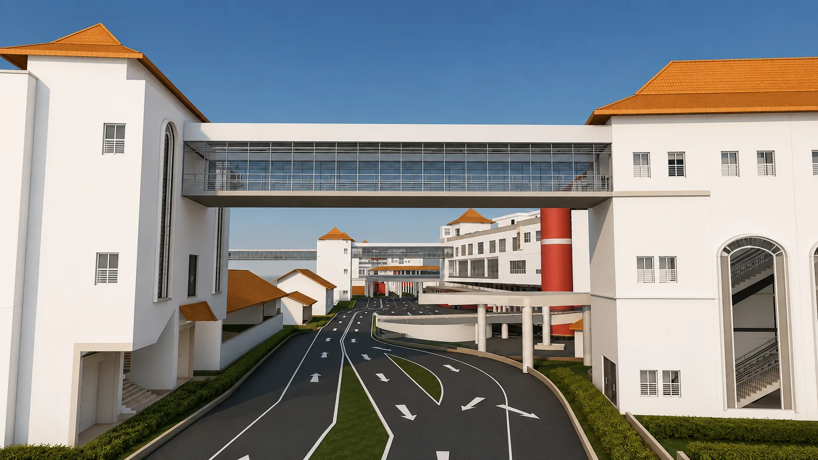
The source article also emphasizes rendering and visualization. IBS Projects prepared rendered images to help the client and project stakeholders understand the proposed terminal, spatial arrangements and architectural character before construction was complete. The published portfolio additionally refers to architectural renderings and walkthrough animations.
For a complex public-infrastructure project, visualization can serve a technical communication purpose as well as a presentation purpose. Stakeholders who do not work directly inside BIM authoring software can still understand passenger spaces, transport circulation, building relationships and major design features through clear rendered views.
The source article notes that the architectural presentation reflects elements of Kandy's traditional cultural identity. Public project information similarly places the terminal within the wider objective of improving Kandy's transport system and urban livability. Visualization therefore helps communicate not only model geometry but also how a major transport facility is intended to sit within an important historic city.
What BIM added to the KMTT delivery
Based on the final case-study source and the published IBS Projects project scope, the principal benefits include:
- Earlier spatial conflict identification: architecture, structure, MEP and specialist systems could be reviewed together before site installation made changes more difficult.
- A shared multidisciplinary review environment: a very large public-transport facility could be examined as interacting systems rather than disconnected discipline drawings.
- Better-informed CCTV review: proposed camera positions, viewing directions and possible physical obstructions could be assessed in three dimensions.
- More reliable specialist-equipment coordination: lifts, escalators, fuel tanks and machine-room equipment could be reviewed against adjacent geometry and services.
- A stronger connection to documentation: coordinated model information supported schedules, detailed drawings and other technical outputs.
- Clearer stakeholder communication: rendered images and walkthrough-style visualization made the spatial intent of the project easier to understand.
Lessons for BIM delivery on large transport hubs
KMTT demonstrates why large transport projects need more than isolated discipline models. Architecture, structure, MEP systems, operational equipment, security devices and public circulation need to be reviewed as interacting systems.
Several practical lessons follow from the project:
- Define model purpose and LOD by intended use. LOD 350 is useful for coordination, but it should not be treated as a blanket claim that every object contains identical detail or information.
- Use project-specific equipment geometry where it matters. Generic families can distort clearances, interfaces and connection conditions when the selected equipment differs from the placeholder.
- Treat clash detection as issue management. A clash list becomes valuable when issues are classified, assigned, reviewed and closed through the responsible disciplines.
- Coordinate machine rooms and specialist equipment early. These areas concentrate equipment, services, access zones and maintenance requirements.
- Use BIM for secondary specialist reviews where useful. CCTV sightline review is one example of the model providing a stronger spatial basis for specialist decisions.
- Connect modelling to documentation and visualization. The same coordinated information can support technical teams, construction documentation and stakeholder communication when it is managed consistently.
Conclusion
The Kandy Multimodal Transport Terminal case study shows how BIM can support coordination across a complex public-transport project where architecture, structure, MEP systems, specialist equipment, security planning, documentation and visualization all interact. The source article records IBS Projects' collaboration with ArchiCAD (Pvt) Ltd in providing BIM support for MAGA Engineering, while the published IBS Projects portfolio records a 1,076,000 sq. ft. scope with LOD 350 architectural and structural models, coordinated building services, machine rooms, specialist equipment, custom families, schedules, detailed drawings and visual outputs.
The central lesson is that the model is most useful when it becomes a shared coordination environment rather than simply a three-dimensional representation. By using BIM to expose interfaces, review potential clashes, examine CCTV positions, coordinate specialist content and communicate design intent, the project team gains a stronger basis for resolving issues before they become more difficult to manage during construction and installation.
Explore the project behind this article
Kandy Multimodal Transport Terminal · KMTT
Review the full 1,076,000 sq. ft. project, LOD 350 building models, MEP scope, specialist equipment, documentation and project gallery.References
- BIMForum (2025) Level of Development (LOD) Specification, Part I. Available at: bimforum.org (Accessed: 21 October 2026).
- IBS Projects (Pvt) Ltd (n.d.) Kandy Multimodal Transport Terminal project case study. Available at: IBS Projects (Accessed: 21 October 2026).
- IBS Projects (Pvt) Ltd (2026) Enhancing Construction Coordination at Sri Lanka's Kandy Multimodal Transport Terminal (KMTT) Through BIM. Source article supplied for revision.
- World Bank (2021) Sri Lanka: Kandy to Redevelop Major Transit Terminal to Support Road Safety, Tourism, COVID Recovery, 22 April. Available at: World Bank (Accessed: 21 October 2026).
- World Bank (2020) Kandy Multimodal Transport Terminal Development Project (P172342): Project Information Document. World Bank Documents & Reports (Accessed: 21 October 2026).
Related Project Case Study
See the Full Kandy Multimodal Transport Terminal BIM Delivery.
Review the 1,076,000 sq. ft. project, LOD 350 building models, coordinated MEP scope, specialist equipment, construction documentation and project gallery.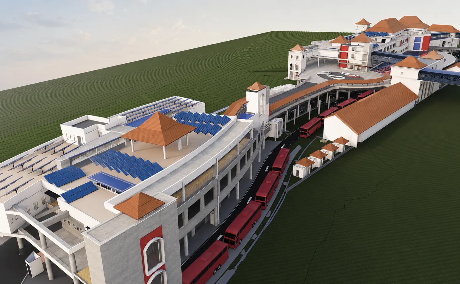
Planning a Transport or Public-Infrastructure BIM Scope?