
Technical Case Study · Aviation & Transport · Sri Lanka
LiDAR Scan-to-BIM for Bandaranaike International Airport: Building a High-Accuracy Digital Record
How survey control, terrestrial LiDAR, point-cloud processing and multidisciplinary BIM modelling transformed incomplete existing-condition information into a structured LOD 500 airport model.

The short answer
IBS Projects used survey control, terrestrial LiDAR, point-cloud processing and multidisciplinary BIM modelling to create a structured existing-condition model of Bandaranaike International Airport's terminal environment where historical as-built information was incomplete or inconsistent. The project source material describes an approximately 90,000 m² LiDAR scan scope, while the IBS Projects portfolio publishes an overall project area of approximately 95,000 m²; the model is described as LOD 500 with an approximately 10 mm modelling target subject to survey control, registration, visibility and verification.
Why existing-condition information mattered at BIA
Bandaranaike International Airport is a long-established operational aviation facility that has developed through multiple generations of construction, alteration and expansion. Airport & Aviation Services (Sri Lanka) records that development of Katunayake Airport began in 1963 and that construction of a larger terminal building, apron and taxiway followed in 1968 (AASL, n.d.). For BIM teams, that history matters because older facilities commonly contain modifications that are only partly reflected in legacy drawings, contractor handover packages or record documents.
The information challenge becomes more important when new development has to connect to an existing terminal. AASL's Phase II Stage 2 programme includes a new Terminal 2, new pier buildings, passenger boarding bridges and a connecting concourse interface with the existing terminal. Reliable knowledge of existing geometry and services is valuable wherever refurbishment, expansion or interface design depends on what is already built.
The IBS Projects Scan-to-BIM scope addressed the practical problem directly: parts of the existing terminal could not be represented confidently from historical two-dimensional documentation alone. The objective was to rebuild the existing environment digitally from measurable site information and create a coordinated model that could provide a more dependable reference for engineering and future project decisions.

The core challenge: incomplete as-built drawings in a complex facility
Conventional BIM authoring often begins with coordinated design drawings and specifications. Existing-building projects can be very different. When record drawings are incomplete, outdated or inconsistent with site conditions, modelling directly from those drawings risks reproducing old assumptions rather than the building that physically exists.
For an airport terminal, architecture, structure, baggage-handling areas, plant rooms, ceiling voids, risers and dense building services occupy the same constrained environment. A small positional error can affect equipment access, proposed service routing, penetrations, clearances or refurbishment planning in another discipline.
IBS Projects therefore treated reality capture as the primary geometric evidence for visible existing conditions, supported by available drawings and project information rather than allowing legacy documentation to control geometry where it conflicted with measured site conditions.
Why LiDAR was the appropriate reality-capture method
Terrestrial LiDAR records large numbers of measured points in three-dimensional space. When scan positions are correctly registered into a common coordinate framework, the resulting point cloud provides a measurable record of visible existing geometry that can be revisited after the field survey is complete.
For BIA, this was useful because the model needed to cover a very large facility and complex technical areas. The source material describes LiDAR capture across approximately 90,000 m², while the published IBS Projects project area is 1,022,570 sq. ft., or approximately 95,000 m². Those figures describe different measures and should not be treated as competing area claims.
LiDAR itself does not produce BIM. It produces measured spatial data. The value comes from the full workflow that follows: survey control, scan coverage, registration, quality checks, point-cloud organisation, interpretation and modelling to the agreed information need and accuracy tolerance.
Standards and guidance directly relevant to the workflow
The final project article keeps the standards list deliberately narrow. These references are relevant to the technical principles of the workflow; their inclusion does not mean every one was contractually mandated on the BIA package. Actual requirements depend on the client information requirements, BIM Execution Plan, survey specification, coordinate system and acceptance criteria.
BIM information-management principles
Relevant to structured creation, exchange, recording, versioning and organisation of model information, including naming, revision and information status.
Information management during asset delivery
Relevant where the Scan-to-BIM model forms part of a defined project delivery process with information requirements, reviews and formal exchanges.
Field testing of terrestrial laser scanners
Provides field procedures for evaluating terrestrial laser-scanner precision and repeatability. It supports instrument and measurement-quality assurance, but does not by itself certify whole-project model accuracy.
Referencing by coordinates
Relevant where survey control, point-cloud data and BIM coordinates must remain consistently referenced within a defined coordinate framework.
Existing-condition / LOD 500 guidance
LOD 500 describes an existing or as-constructed condition developed from observation, field verification or interpolation. It does not define a millimetre accuracy by itself.
The IBS Projects survey-to-BIM workflow
Establish the spatial framework
Building survey information, grid establishment, levels and control references create the stable framework needed to align scan stations and BIM geometry.
Capture multiple LiDAR stations
Scanner positions are planned around coverage, overlap, access restrictions and occlusions so the terminal can be captured from enough viewpoints to reduce hidden areas.
Register and quality-check the point cloud
Individual scans are aligned into a common coordinate framework and checked for residuals, overlap, double surfaces, level consistency and localised misalignment.
Prepare the cloud for BIM authoring
Large datasets are organised into practical views, sections and linked regions so modellers can work from controlled measured evidence rather than an unstructured visual background.
Model architecture, structure and services
Visible existing conditions are interpreted from the processed point cloud and available project information, with detail kept proportional to the intended coordination and information use.
Verify model geometry against the scan
Plans, sections, critical dimensions, grids, levels, equipment positions and selected service routes are compared back to the scan before information is accepted for downstream use.
Establish survey control before detailed modelling
Point clouds become useful for coordinated BIM only when they are tied to a stable spatial framework. Grid lines, levels, datums and control references connect field measurements, scan stations and the BIM authoring environment. Where local or site coordinate systems are used, the transformation into the project coordinate environment should be documented so later survey information and discipline models can remain aligned.
Capture the existing terminal from multiple positions
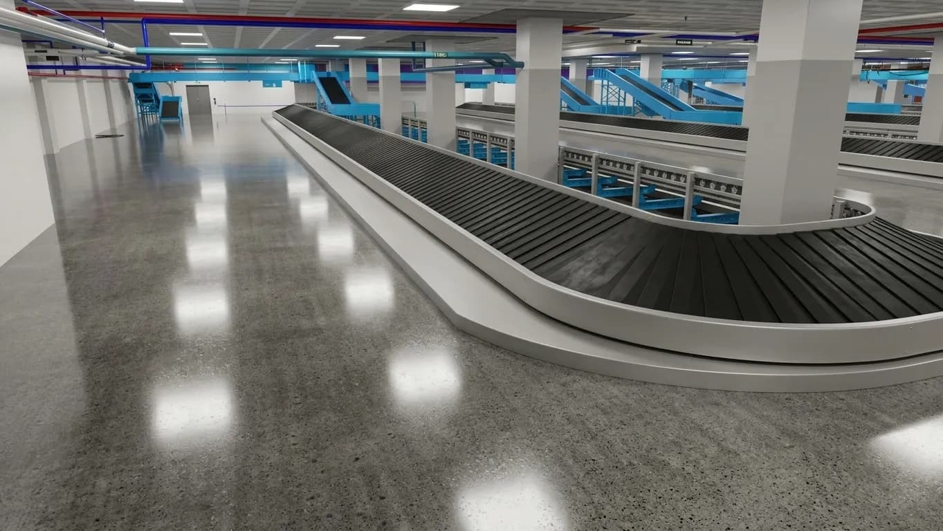
A large operational terminal cannot be captured reliably from a small number of scan positions. Walls, columns, equipment, baggage systems, furniture, suspended services and plant-room machinery all create occlusions. Multiple stations are therefore needed to provide overlapping lines of sight and improve coverage.
Operational constraints also matter. Security-controlled areas, passenger movement, service access and availability of plant rooms can influence when and where scanning is possible. Missing coverage identified after demobilisation can be expensive to recover, so field planning, scan naming and coverage checks are part of the BIM quality chain rather than separate administrative tasks.
Register and quality-check the point cloud
Individual scans have to be registered into a common coordinate system. Registration quality is one of the most important controls in Scan-to-BIM: a scanner can have strong instrument precision while poor station alignment still creates duplicated or shifted geometry in the combined cloud.
Useful checks include control-point residuals, registration residuals, overlap between stations, visible double surfaces, floor and soffit levels and localised misalignment. ISO 17123-9:2018 is relevant to scanner precision and repeatability, but the final reliability of the project model also depends on survey control, registration, environmental conditions and the modelling process.
Prepare the point cloud for practical BIM authoring
Raw point clouds can contain very large numbers of measured points. Before modelling, the information should be organised into manageable linked datasets or regions, with appropriate sections and slices used for interpretation. Historical drawings can still help identify systems, element names and concealed information, but measured geometry should control visible existing conditions unless the project requirements state otherwise.
Develop architecture, structure and building services from measured evidence
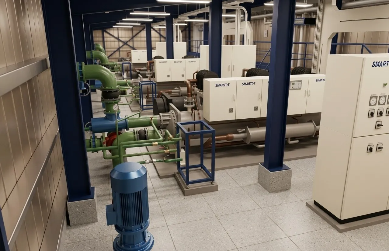
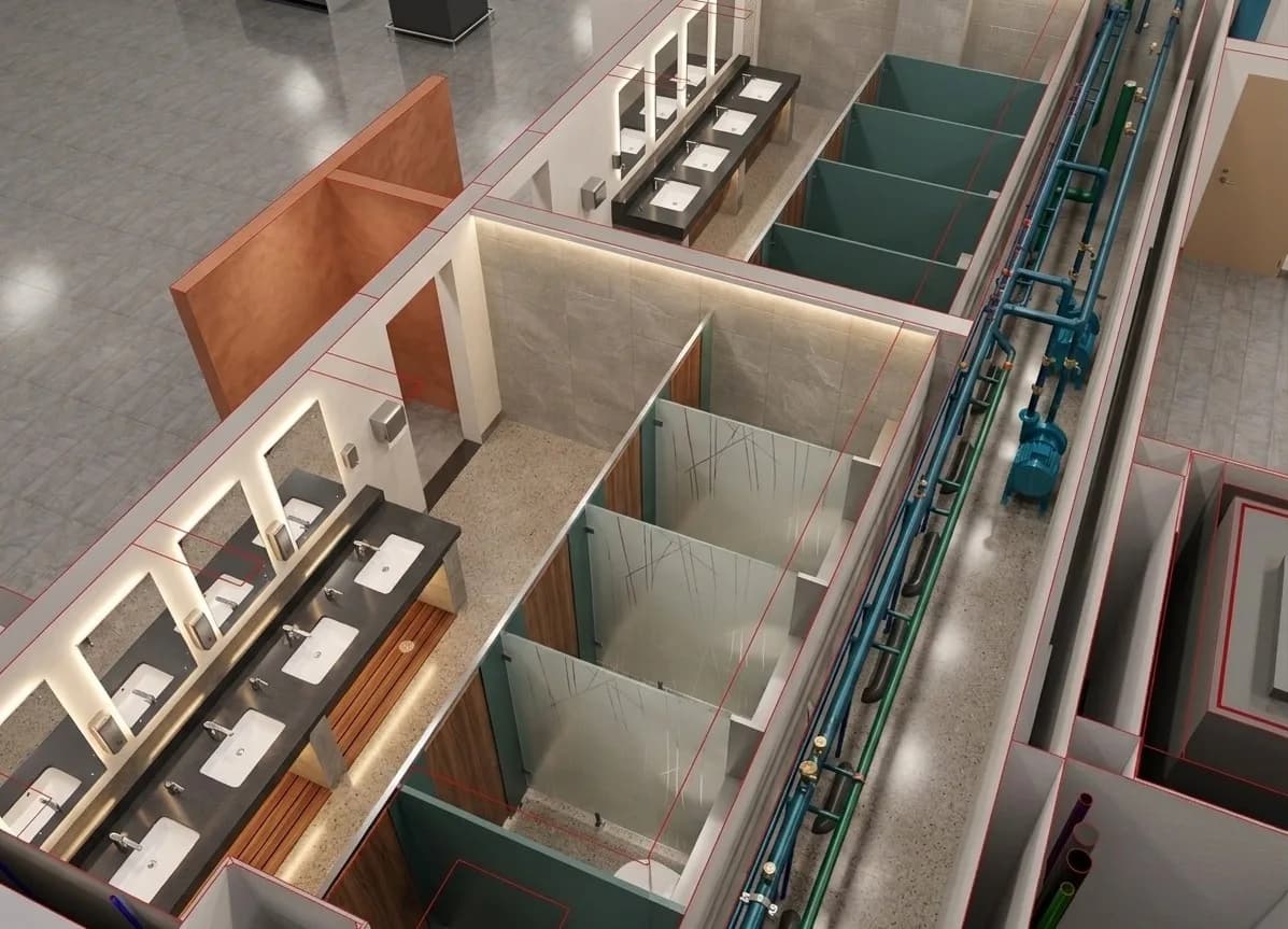
IBS Projects developed a multidisciplinary representation of the terminal environment using the processed point cloud as the geometric reference. Architectural elements establish rooms, walls, floors, ceilings, openings and circulation zones; structural modelling captures visible supporting geometry; building-services modelling records mechanical, electrical, plumbing and fire-protection systems where those elements fall within scope and are sufficiently observable.
Plant rooms and service zones have particularly high coordination value because equipment, pipework, ducts, cable containment and access zones compete for space. The modelling objective is not maximum visual detail. It is to capture the geometry that supports the intended engineering, coordination and documentation use without adding unnecessary model weight.
Understanding the approximately 10 mm modelling target
Accuracy is often misunderstood in Scan-to-BIM because three related concepts are easily combined: instrument precision, registered point-cloud accuracy and model-to-reality accuracy.
- Instrument precision describes scanner measurement behaviour under defined conditions. ISO 17123-9:2018 provides field procedures for evaluating terrestrial laser-scanner precision and repeatability.
- Registration accuracy describes how consistently separate scan stations have been aligned into the common project coordinate system.
- Model accuracy describes how closely the authored BIM geometry represents the accepted point-cloud or survey evidence for the element being modelled.
A straight wall with dense unobstructed points can generally be interpreted more confidently than a flexible cable, reflective surface, concealed pipe, moving object or equipment component hidden behind other services. The approximately 10 mm modelling target should therefore be understood as a project objective subject to the quality and visibility of the underlying evidence, not as a guarantee that every point on every object is within exactly 10 mm.
What LOD 500 means in an existing-airport model
The IBS Projects portfolio describes the AASL Terminal Building delivery as LOD 500. BIMForum's 2025 guidance treats LOD 500 as an existing or as-constructed condition developed through observation, field verification or interpolation. The accuracy of that model element must still be stated separately.
That distinction is important for Scan-to-BIM. LOD 500 does not mean every object must contain fabrication-level detail, and it does not automatically mean that an LOD 500 element is geometrically "more detailed" than LOD 400. A field-verified wall, duct or equipment item can be LOD 500 while its geometric complexity remains appropriate to the intended project use.
For BIA, the practical objective was a dependable digital representation of observable existing conditions, organised at a level that could support coordination, future project decisions and downstream information use.
Why an operational airport makes Scan-to-BIM more demanding
Airports combine the scale and movement of a major public building with the technical density and security requirements of infrastructure. Existing-condition capture has to account for conditions that are less common in ordinary commercial buildings:
- restricted and security-controlled areas can limit scanner access and require planned survey windows;
- passengers, temporary obstructions and operational equipment can create moving objects or incomplete lines of sight;
- plant rooms, ceiling spaces and service corridors contain dense overlapping systems where occlusion is common;
- long building histories can produce differences between legacy drawings and present physical conditions;
- large floor plates magnify small coordinate or level inconsistencies when survey control is weak; and
- future expansion interfaces need dependable understanding of existing structure, levels, circulation and services near connection zones.
These constraints reinforce the need for a traceable workflow where survey evidence, modelling assumptions, unresolved areas and information status are made explicit rather than hidden inside a visually convincing model.
Information management: from point cloud to usable asset information
A Scan-to-BIM project is not complete when the geometry looks correct. Other project participants need to understand what has been modelled, which source information was used, which areas were observed or verified, where assumptions remain and how revisions are controlled.
ISO 19650-1:2018 establishes BIM information-management principles, while ISO 19650-2:2018 addresses information management during project delivery and information exchanges. These are the two ISO 19650 references kept in this case study because they are directly relevant to organising and exchanging project information. Their inclusion should not be read as evidence that the BIA package was contractually delivered to ISO 19650 unless the project requirements confirm it.
Results: a more dependable digital foundation for future airport work
The practical value of the BIA Scan-to-BIM delivery is the reduction of uncertainty around existing conditions. Instead of depending only on historical drawings, project teams gain a structured three-dimensional reference derived from measured site information.
- Improved existing-condition documentation: terminal areas with missing, incomplete or difficult-to-reconcile conventional as-built information can be represented in one coordinated digital environment.
- Better renovation and interface planning: proposed work can be reviewed against a structured representation of the existing building.
- Clearer multidisciplinary coordination: architecture, structure and building services can be reviewed together, especially in plant and service zones.
- Reduced repeat measurement: verified model information can reduce the need for repeated basic site measurement where the required geometry is already represented and remains current.
- A stronger base for downstream design: clash review, option studies, quantities and detailed design can use the model where those uses respect its stated accuracy and information scope.
- Longer-term digital value: the model can support later asset-information use when it is maintained, governed and updated rather than treated as a one-time visual deliverable.
Lessons for high-accuracy Scan-to-BIM projects
The Bandaranaike International Airport case study reinforces four practical principles. First, reality capture is only as reliable as the survey control and registration behind it. Second, a dense point cloud is not the same thing as BIM: interpretation, scope control, information structure and verification are still required. Third, LOD and measurable accuracy have to be defined separately. Finally, models intended to support future refurbishment or asset use need traceable information status, not just detailed geometry.
For clients procuring Scan-to-BIM, the brief is stronger when it defines required areas, element classes, coordinate system, target accuracy or Level of Accuracy, model-development requirements, required parameters, file formats, review method and intended model uses. That allows the survey and BIM teams to focus capture and modelling effort on information that has a real downstream purpose.
Conclusion
The Bandaranaike International Airport project shows how LiDAR-supported Scan-to-BIM can convert an existing facility with incomplete historical documentation into a more dependable digital working environment. Survey grids and levels, large-scale LiDAR capture, point-cloud registration, multidisciplinary BIM authoring and verification were combined to develop an LOD 500 existing-condition model intended to support future coordination and decision-making.
The key lesson is that high-quality Scan-to-BIM is not defined by scanner technology alone. Dependable results come from the complete information chain: survey control, capture coverage, registration quality, coordinate management, disciplined modelling, realistic accuracy statements, documented assumptions and controlled information exchange.
Explore the project behind this article
AASL Terminal Building · Bandaranaike International Airport
Review the published 1,022,570 sq. ft. project, coordinated terminal BIM views, walkthrough and LOD 500 existing-condition delivery.References
- Airport & Aviation Services (Sri Lanka) (AASL) (n.d.) Aviation history. Available at: airport.lk (Accessed: 14 October 2026).
- Airport & Aviation Services (Sri Lanka) (AASL) (2025) AIC A 02/25: Construction of new terminal building, associated new pier buildings and passenger boarding bridges at Bandaranaike International Airport Colombo, 29 January 2025. Available at: airport.lk.
- BIMForum (2025) Level of Development (LOD) Specification. Available at: bimforum.org.
- IBS Projects (n.d.) AASL Terminal Building – project case study. Available at: IBS Projects (Accessed: 14 October 2026).
- International Organization for Standardization (ISO) (2018a) ISO 19650-1:2018, Organization and digitization of information about buildings and civil engineering works, including BIM – Information management using BIM – Part 1: Concepts and principles. Available at: ISO.
- International Organization for Standardization (ISO) (2018b) ISO 19650-2:2018, Organization and digitization of information about buildings and civil engineering works, including BIM – Information management using BIM – Part 2: Delivery phase of the assets. Available at: ISO.
- International Organization for Standardization (ISO) (2018c) ISO 17123-9:2018, Optics and optical instruments – Field procedures for testing geodetic and surveying instruments – Part 9: Terrestrial laser scanners. Available at: ISO.
- International Organization for Standardization (ISO) (2019) ISO 19111:2019, Geographic information – Referencing by coordinates. Available at: ISO.
Related Project Case Study
See the Full AASL Terminal Building BIM Delivery.
Review the 1,022,570 sq. ft. project, LOD 500 existing-condition BIM scope, walkthrough and coordinated terminal model views.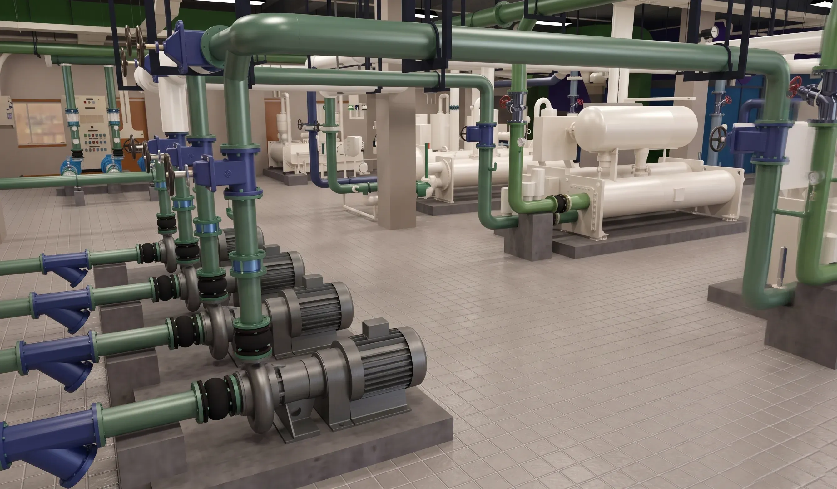
Planning a Complex Existing-Facility Scan-to-BIM Scope?